Table of Contents
 Cette page n'est pas encore traduite entièrement. Merci de terminer la traduction
(supprimez ce paragraphe une fois la traduction terminée)
Carte électronique (version 1.0)
The schematic of the board is available in PDF format. Prin in A3 for best resolution.


Parts List catalog
| Quantity | Component | Value |
| 2 | C1,C3 | 220µF électrolytiques 16V |
| 1 | C2 | 100nF tantale |
| 8 | C4,C5,C6,C7,C8,C9,C10,C11 | 10µF céramique |
| 11 | C12,C13,C14,C15,C16,C18,C19,C20,C21,C22,C23 | 0,1µF tantale |
| 1 | C17 | 1µF tantale |
| 2 | D1,D2 | 1N5820 |
| 2 | D3,D4 | LED rouge |
| 6 | D5,D6,D13,D14,D15,D16 | LED verte |
| 2 | D7,D8 | 10BQ015 (CMS) ou 1N5819 |
| 4 | D9,D10,D11,D12 | 1N4148 |
| 2 | IC1,IC8 | ULN2003 |
| 1 | IC2 | DS18B20 |
| 2 | IC3,IC6 | CNY74-4 |
| 1 | IC4 | MAX3232 |
| 1 | IC5 | MAX6369 |
| 1 | IC7 | MCP3204 |
| 1 | J1 | Connecteur 40 Raspberry Pi B+/2B |
| 4 | J4,J8,J12,J14 | Jack 3,5mm |
| 3 | J2,J6,J10 | RJ 12 : TX RPTER, RX RPTER, LINK |
| 1 | J16 | Connecteur-DC-2.1mm |
| 4 | K1,K2,K3,K4 | RT314A12 |
| 1 | L1 | 330 µH - 1 A |
| 12 | R1,R2,R3,R4,R5,R6,R7,R8,R41,R42,R43,R44 | 470 1/4W |
| 4 | R9,R11,R13,R16 | 1K 1/4W |
| 4 | R33,R34,R35,R36 | 220 Ohms 1/4W (pour entrées sous 5V) |
| 7 | R10,R12,R22,R37,R38,R39,R40 | 10K 1/4W |
| 2 | R14,R17 | 1K potentiomètre linéaire |
| 2 | R15,R18 | 10K potentiomètre linéaire |
| 3 | R19,R20,R21 | 4,7K 1/4W |
| 2 | R23,R24 | 10 1/4W |
| 8 | R25,R26,R27,R28,R29,R30,R31,R32 | 0K 1/4W |
| 4 | Tr1,Tr2,Tr3,Tr4 | ETAL P1200 |
| 1 | X1 | LM2575T-5 |
| 1 | X2 | KIM-055L |
| 4 | DIVERS | Entretoises 10mm M3 femelle/femelle + vis M3 |
| 1 | DIVERS | Connecteurs SECABLE HE14 pas de 2,54mm droite 1×36 |
Step by step Assembly description
1. The Power supply assy
Power supply with module KIM-055L

The components list to be installed :
- Connector DC 2,1mm J16 or J17 Screw terminal.
- Diode D1 1N5820 C1 and
- C3 capacitor 220μF 16V
Test of the 5V output voltage

2. PTT / SQUELCH assy
PTT/SQUELCH assemby section

The components list to be installed:
- IC8 ULN2003
- IC3 CNY74-4
- R1 à R8 470 Ω
- R9, R11 1 kΩ
- R10, R12 10 kΩ
- D3, D4 Led red 3mm (with + on resistor side, the longer leg)
- D5, D6 Led green 3mm (with + on resistor side, the longer leg)
- D7, D8 Diodes 10BQ015
3. AUDIO IN/OUT assy


The components list to be installed:
- C4 à C11 Capacitor 10μF
- R13 et R16 1 kΩ
- R14 et R17 Potentiometer 1 kΩ
- R15 et R18 Potentiometer 10 kΩ
- J4,J8,J12,J14 Connector jack 3,5mm (It is possible to install PIN to solder J5,J9,J13,J15). It is required to file or grind the 4 rear connections on the SVXLink Card version 1.0.
- TR1 à TR4 Isolation Transformer ETAL P1200 (There is a possible alternative see above picture).
- J2,J6,J10 Connector RJ12 or PINs to solder
<note warning>
Mistake in pin description on Board
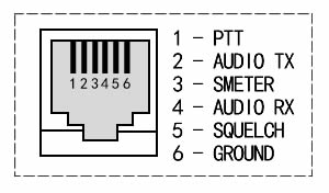 </note>
THE ASSEMBLY IS TERMINATED FOR THE MINIMUM VERSION OF THE CARD. NOW WE ARE GOING TO START THE OPTIONAL PARTS. QR:THE CONNECTOR 2 × 20 pins OF THE RASPBERRY PI WILL BE WELD IN THE LAST TIME. IF YOU USE ONLY THE RELAY VERSION WITHOUT LINK, THIS PART MAY BE NOT WELDED.
4. OPTO INPUTS assy


The components list to be installed:
- R33 à R36 220 Ω (This value can be changed according to the input voltage. Here it's for 5V)
- J26 connector 2×5 pins
- IC6 CNY74-4
- R37 to R40 10 kΩ
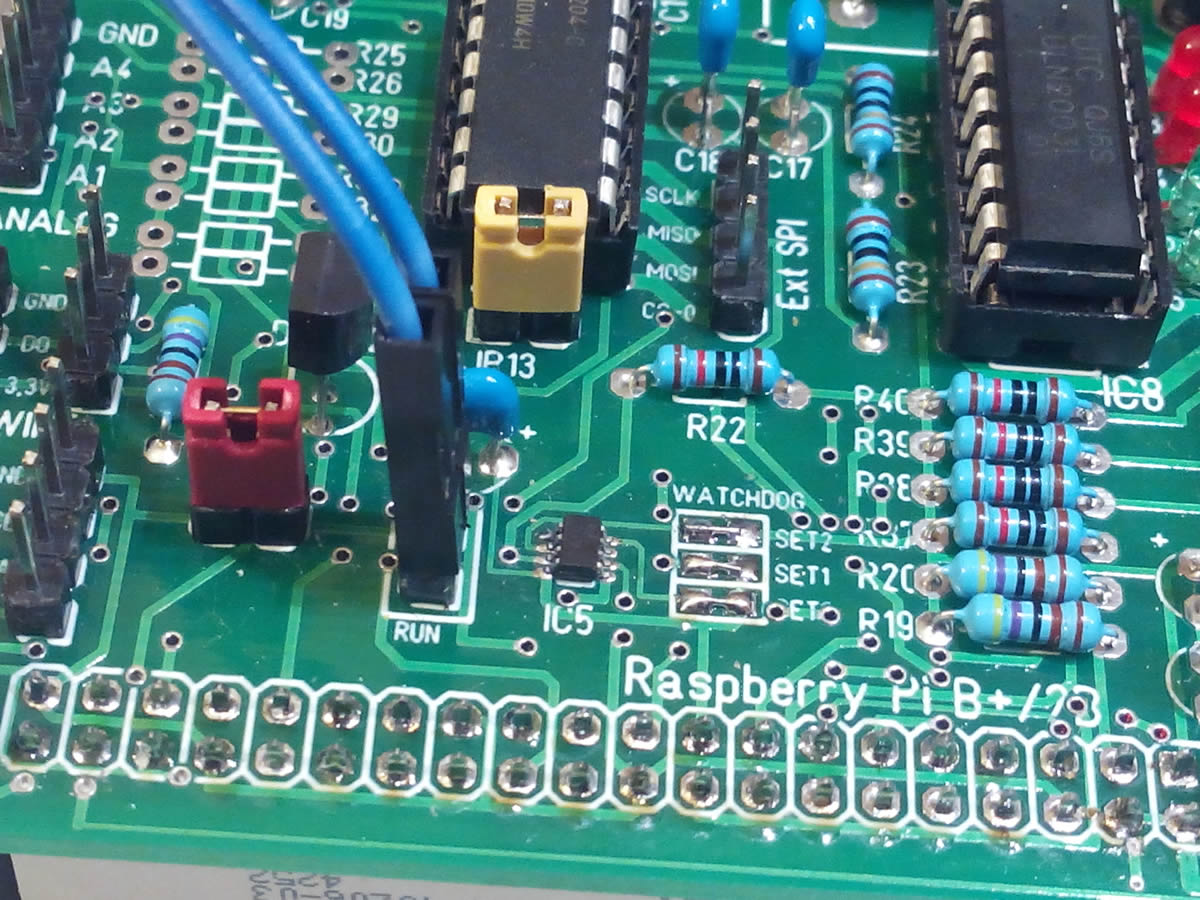
5. WATCHDOG assy

The components list to be installed:
- IC5 MAX6369
- C14 Capacitor 0,1μF
- PIN 2×1 Weld the 2 connectors. One is useful to activate the Watchdog and the other (RUN) to connect the RUN or P6 connector of release (Reset) of the Raspberry Pi. SET0 SET1 SET2 are jumpers (solder) to determine the time before reset if it does not send a signal.
A Watchdog “MAX6369” is a standalone CI. If the component does not receive a voltage pulse (System crash) in a defined period, it will reset the system.

As boot starting time exceeds 10 seconds, it is recommended to set the detection time (timeout) at maximum. As indicated in the above table, the 3 jumpers SET0, SET1 and SET2 needs to be closed (Weld the three pairs of squares).
6. Connector I2C assy

The installation is just prolonging the I2C connections that are on the Raspberry Pi.
7. The 1 WIRE assy

The components list to be installed:
- J20 and J21 Installation 2 connectors pin 3×1, for 1WIRE externals sensors.
- IC2 DS18B20 temperature sensor
- R21 4,7 kΩ resistor

Here an overall picture at this level of assembly.
8. Output on Relay assy

The components list to be installed:
- IC1 ULN2003
- D13 à D16 green diode 3mm, (with + on resistor opposite side, the longer leg)
- R41 à R44 470 Ω resistors
- D9 à D12 diodes 1N4148
- K1 à K4 relay 12V/16A
- J28 à J31 Terminal with 3 blocks Screw
9. Analogic/Digital converter assy

The components list to be installed:
- IC7 MCP3204 R23 to R24 10 Ω resistors
- C15 to C18 0,1 µF
- the resistors R25 to R32 (bridge voltage divider), will be determined depending on the voltage to be measured.
- It remains the connector Pin J25 5×1 and the connector Pin 2×1 for the jumper JP13 used to connect the grounds Card/measures if necessary.
10. RS232 Port assy

The components list to be installed:
- IC4 MAX3232
- C19 à C23 capacitor 0,1µF
- Connector PIN 3×1 will be used to connect RXD,TXD,GNG on a DB9 connector for example.
11. Connector Raspberry Pi assy


The components list to be installed:
- Connector 40 pins female
The Raspberry Pi is fixed on the card with 4 spacers 10mm and 8 screws M3, this is a temporary assembly because you'll have to add spacers to secure definitively the card in a box.
12. Final result of assy


13. GPIO used on the Raspberry Pi

