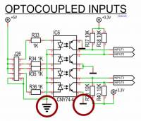
Opto-isolator inputs configuration
File /etc/rc.local
Edit the file with this command (Inserted at the end of the file just BEFORE exit 0 )
sudo nano /etc/rc.local
#INPUTS
echo "24" > /sys/class/gpio/export &
sleep 2
echo in > /sys/class/gpio/gpio24/direction
echo "25" > /sys/class/gpio/export &
sleep 2
echo in > /sys/class/gpio/gpio25/direction
echo "26" > /sys/class/gpio/export &
sleep 2
echo in > /sys/class/gpio/gpio26/direction
echo "27" > /sys/class/gpio/export &
sleep 2
echo in > /sys/class/gpio/gpio27/direction
Tests of opto-isolator inputs
<note important>

![]() For SVXCard version 1.0 (2015) :
The ground at the input of the optocoupler is not connected to the ground of the main board. So you need to power your inputs with an external power (outside the main board). So you MUST IMPERATIVELY connect your input on a pin that is not at + 5V (board).
For SVXCard version 1.0 (2015) :
The ground at the input of the optocoupler is not connected to the ground of the main board. So you need to power your inputs with an external power (outside the main board). So you MUST IMPERATIVELY connect your input on a pin that is not at + 5V (board).
A second way is to use the distributed +5V to feed the external contact. In this case, it will be necessary to link pine 9 or 10 of connectors J26 (screenprinting OPTO INPUTS) with the mass plan. In this case, the opto-isolation is not operational because the power supply comes from the card. </note>
The following python code allows you to check the states of each of the 4 inputs.
sudo nano test-input.py
- | test-inputs.py
#!/usr/bin/python
import time
from RPi import GPIO
GPIO.setmode(GPIO.BOARD)
GPIO.setup(18, GPIO.IN, pull_up_down=GPIO.PUD_DOWN)
GPIO.setup(22, GPIO.IN, pull_up_down=GPIO.PUD_DOWN)
GPIO.setup(37, GPIO.IN, pull_up_down=GPIO.PUD_DOWN)
GPIO.setup(13, GPIO.IN, pull_up_down=GPIO.PUD_DOWN)

while True:
    inputval1 = GPIO.input(18)
    inputval2 = GPIO.input(22)
    inputval3 = GPIO.input(37)
    inputval4 = GPIO.input(13)
    print "INPUT1="+str(inputval1) +  ",INPUT2="+str(inputval2) + ",INPUT3="+str(inputval3) +   ",INPUT4="+str(inputval4)

    time.sleep(1)
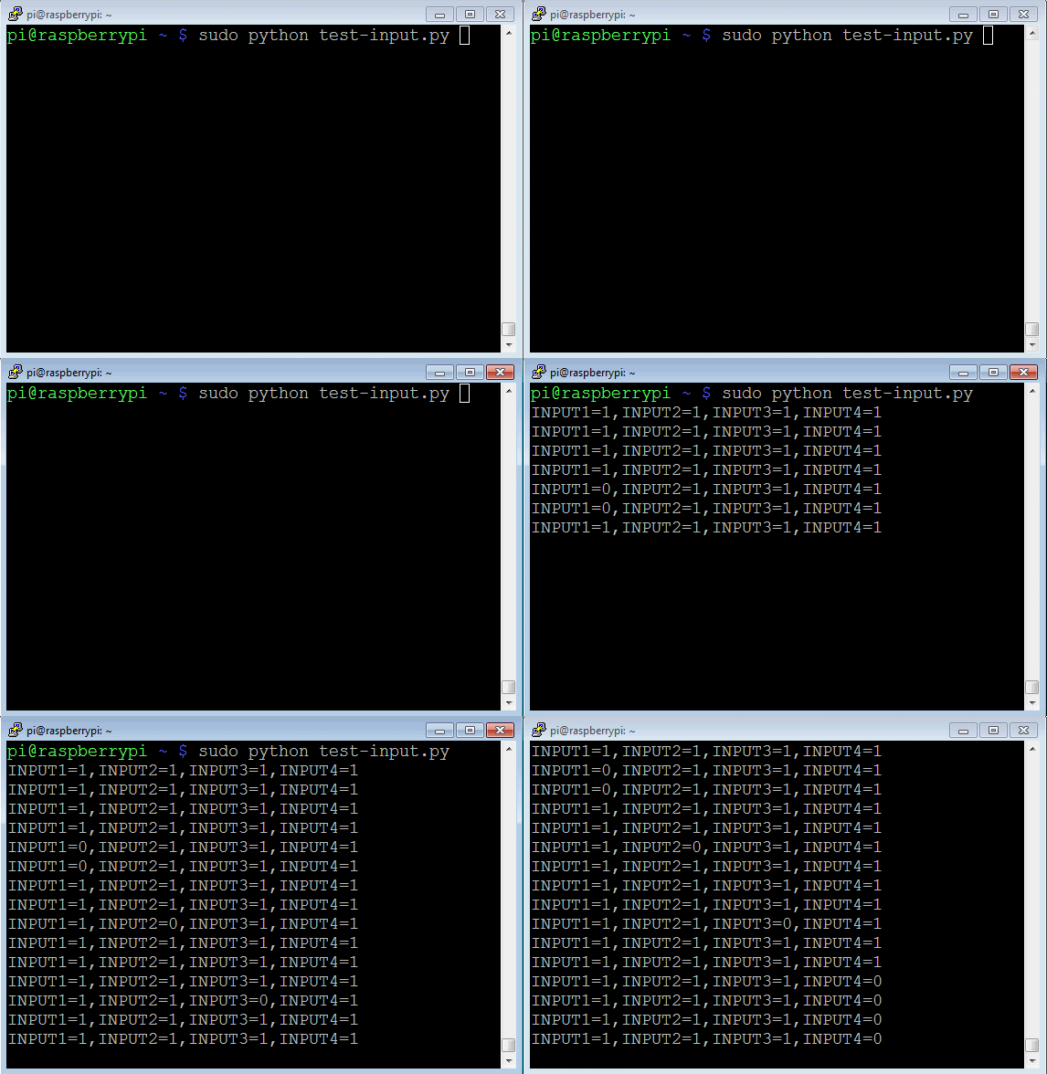
The tests will be launch with this command
sudo python test-input.py
Here are the results of the tests for the channels 1 to 4.

CTRL-C to exit