Analogs inputs configuration
Le Raspberry Pi (2) est dépourvu d'entrées analogiques. La carte SVXLink Card est équipée d'un convertisseur assurant cette fonction (IC7 MCP3204) pour 4 mesures. <note important>Les entrées analogiques doivent évoluer uniquement dans la plage de tension 0 à 3,3 V</note>
Il faut dans un premier temps mettre en route le bus SPI au démarrage.
File /boot/config.txt
Edit the file /boot/config.txt and add this line: Run editor with this command
sudo nano /boot/config.txt
then add this line in the file at the end of the page
dtparam=spi=on
Installation of the python module for the SPI bus management
For software modules installation, execute these commands
sudo apt-get install python-dev python-pip
sudo pip install spidev
Acquisition tests of input analogs channels
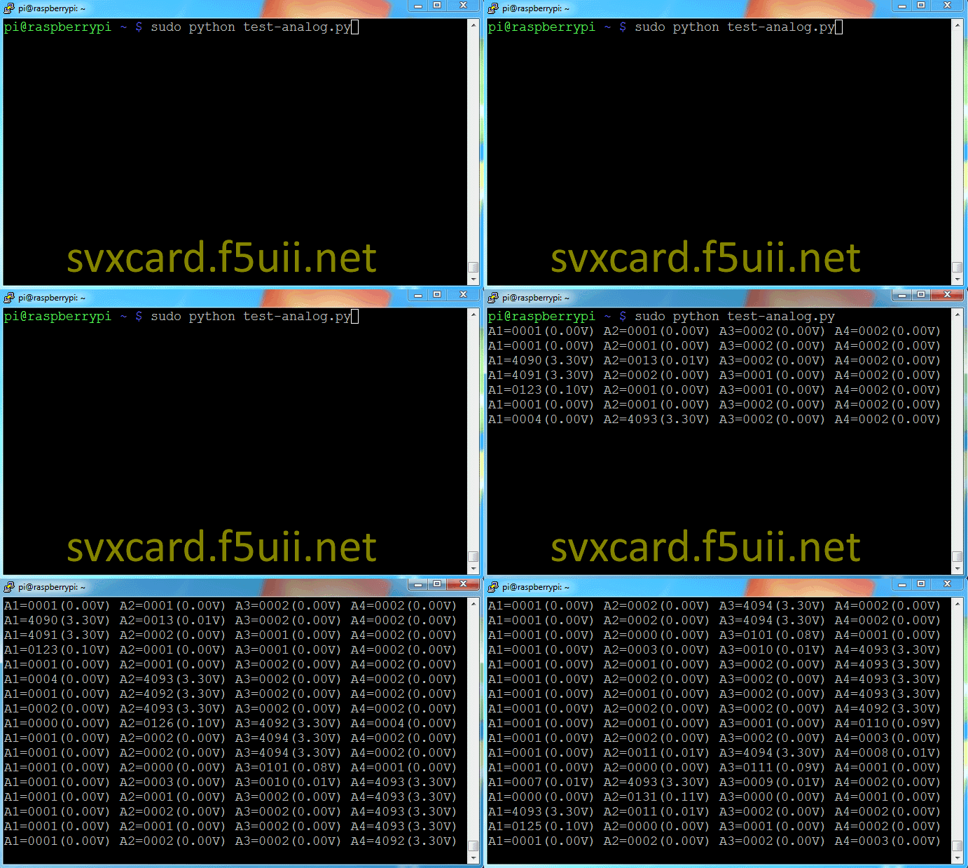
To verify it works, the following python code will allow you to read the values (and display in points and voltage of the 4 inputs).
- | test-analog.py
#!/usr/bin/python
#
# MCP3204/MCP3208 sample program for Raspberry Pi
#
# how to setup /dev/spidev?.?
# $ sudo modprobe spi_bcm2708
#
# how to setup spidev
# $ sudo apt-get install python-dev python-pip
# $ sudo pip install spidev
#
import spidev
import time

class MCP3208:
	def __init__(self, spi_channel=0):
		self.spi_channel = spi_channel
		self.conn = spidev.SpiDev(0, spi_channel)
		self.conn.max_speed_hz = 1000000 # 1MHz

	def __del__( self ):
		self.close

	def close(self):
		if self.conn != None:
			self.conn.close
			self.conn = None

	def bitstring(self, n):
		s = bin(n)[2:]
		return '0'*(8-len(s)) + s

	def read(self, adc_channel=0):
		# build command
		cmd = 128 # start bit
		cmd += 64 # single end / diff
		if adc_channel % 2 == 1:
			cmd += 8
		if (adc_channel/2) % 2 == 1:
			cmd += 16
		if (adc_channel/4) % 2 == 1:
			cmd += 32

		# send & receive data
		reply_bytes = self.conn.xfer2([cmd, 0, 0, 0])

		#
		reply_bitstring = ''.join(self.bitstring(n) for n in reply_bytes)
		# print reply_bitstring

		# see also... http://akizukidenshi.com/download/MCP3204.pdf (page.20)
		reply = reply_bitstring[5:19]
		return int(reply, 2)

if __name__ == '__main__':
		spi = MCP3208(0)

		count = 0
		a0 = 0
		a1 = 0
		a2 = 0
		a3 = 0

		#while count <= 11:
		while True:
			count += 1
			a0 += spi.read(0)
			a1 += spi.read(1)
			a2 += spi.read(2)
			a3 += spi.read(3)

			if count == 10:
				print "A1=%04d(%.2fV) A2=%04d(%.2fV) A3=%04d(%.2fV) A4=%04d(%.2fV)" % (a0/10, a0/10*3.3/4096, a1/10, a1/10*3.3/4096, a2/10, a2/10*3.3/4096, a3/10, a3/10*3.3/4096,)
				time.sleep(1)

				count = 0
				a0 = 0
				a1 = 0
				a2 = 0
				a3 = 0
Here is a test sequence, with the voltage setting of 3.3V (taken on the 1WIRE pin), directly sent to pins 1 to 4 of the MCP3204 (IC7)
